| |
Ray
Kohls CUSTOM
AATV s |
Click on Photo |
| |
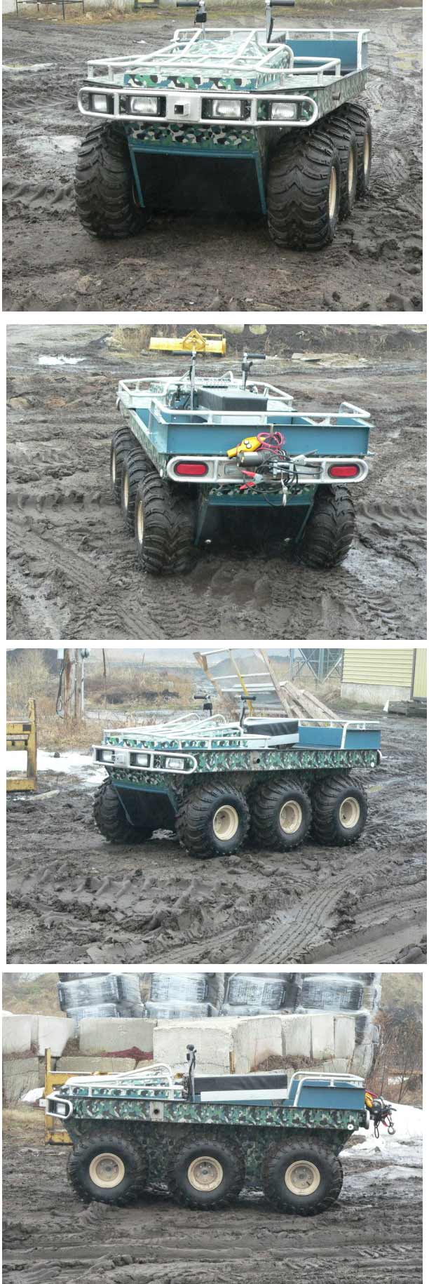
Bushwacker ATV
4 Seater Amphibious ATV
INSTALLMENT #1
The Bushwacker ATV design started back in the early 2000’s.
Like many of us I owned different “4-wheeler ATV’s”,
some were better than others. They served their purpose being
mainly a one-person fun machine. If you tried as I did to push
it beyond its intended use you usually were rewarded with a
high cost repair, disappointment, or both.
I generally found them hard to repair and expensive. I remember
the fun of a group ride following the snowmobile trails only
to be stopped by a river or lake. This was the “end of
the trail”. We hated it and would try and find a way to
continue but usually that was as far as we could go. We then
tried different mods to our ATV’s like sealed intakes,
floatation devices etc. The results were interesting.
We needed to take a different approach. I started looking for
alternatives, why re-invent the wheel? This led us to check
out the existing AATV’s, I remember my first test ride,
I went over a ploughed frozen cornfield, I couldn’t believe
the rough ride, and also it was too heavy and too wide. We needed
something in the 50-52” tire width maximum to enable us
to ride the existing trails and thick wooded off-road stuff.
I spend months looking for a suitable product, and finally did
find one called a Hoot, however it was a one person ATV and
I wanted a little more utility.
I had to design my own. So after reading Route 6x6 forum for
a few years (where AATV owners talked about improvements and
their future dream machine), I started making a short list of
the features I would like to incorporate in a new AATV. The
result is the Bushwacker ATV.
More to come soon.......Ray Kohls |
 Click image
 Click image
|
| |
|
|
| |
INSTALLMENT #2
Bushwacker ATV Design
So where do we start? We probably all have a picture in
our mind of the finished product, but we need to lay down a list
of features and benefits we would like to see incorporated in
our new design. We need to ask ourselves.
1. How many will it seat?
2. How much room for storage?
3. What are the approximate dimensions?
4. What is the payload on land/water?
5. What is our target weight?
6. How many wheels?
7. Do we need a trailer to move it or can it fit on a pickup?
8. How much ground clearance?
9. What type/size of tires/rims?
10. What material will the hull be constructed of?
11. What engine/manufacturer/Hp?
12. What transmission?
And so on…………………
The answer to these questions will shape the appearance and performance
of your machine.
An easy way to start is to draw or sketch your ideas on paper.
Then use a computer program to draw your design to scale.
I like Corel Draw, but there is a lot of drawing programs out
there use something that you are comfortable with.
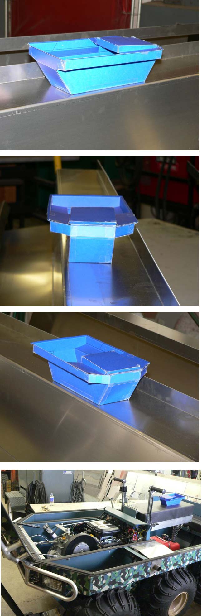
Once I completed this task, I printed it out on construction paper,
cut it out and scotch taped it together. It’s amazing how
this scale model will help you visualize the different components
and how they relate to each other. The following is a list
of the features and benefits I developed for the Bushwacker ATV.
Features
Benefits
All Aluminum Construction Light,
strong, easy to
modify/repair
Amphibious Land
or Water
Unique Hull
Stability, 6” Freeboard, Higher
penetration
in dense under brush.
Front Opening Hood Easy
access for inspection service
Seats 4 Flexibility
between people/cargo
Suspension Seat Soft
ride, comfortable, no loss of control.
5” Dense Foam Seats Comfort
4 Cooling Fans Cooler
engine, transmission, exhaust temperatures
23 Hp Vanguard w/manual Performance,
run accessories recoil backup, oil cooler, fan without draining
battery cooled, 50 amp. Alternator
Tuff Torq KT-35 Transmission Proven in
J.D. Gators, Club Cadet, Wet brakes, Diff. Lock, Constant mesh,
high torque ratings.
25” x 9” x 12” wide Mudlite
6 ply, aggressive tread, lightweight tough tire
Double
Bead Lock Rims
Hold air better, Can run Low
psi.
50” width overall
Run State trails, Fits between truck
wheel wells, Run tight trails/bush
Push Button Diff-Lock Lockup
6 wheels for traction
Dual Winch Positions
Front or back winching, portable
2 Double Lip Axle Seals
Better water sealing, per Axle
#60 HD Chain/ 1 ?” 4140
Higher torque ratings, less solid axles chain
stretch, Higher load capacity
9” ground clearance
Less hang-ups
Full High Density Poly Slides
off of obstacles,
Skid Plate
protects hull
4 Halogen Headlights,
2 Outside headlights 2 Backup Lights, Tail illuminates
side of trail
Lights, Hood Light before you turn
Quick Disconnect Gas
Take tank to gas station, fill Tank, w/primer tank
out of vehicle
Next installment, lets cut and bend some metal |
 Click image
 |
| |
|
|
| |
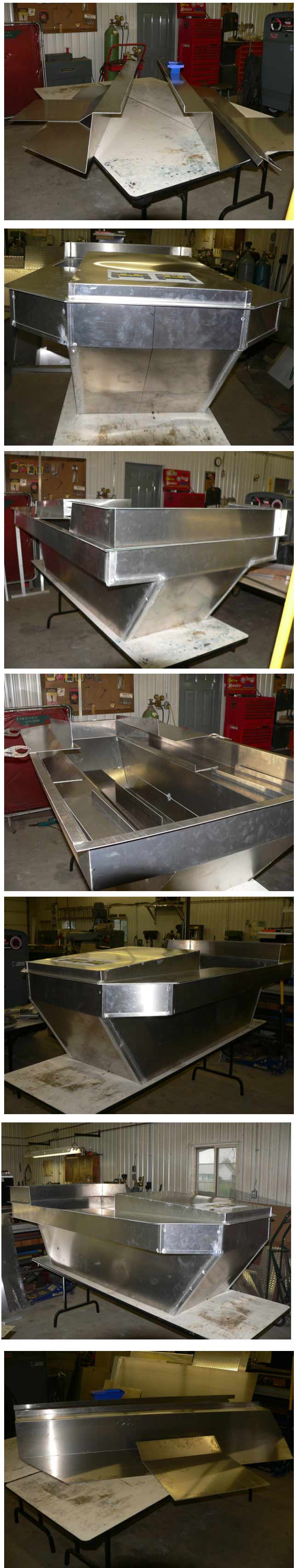
INSTALLMENT #3
Bushwacker ATV Cut and Bending
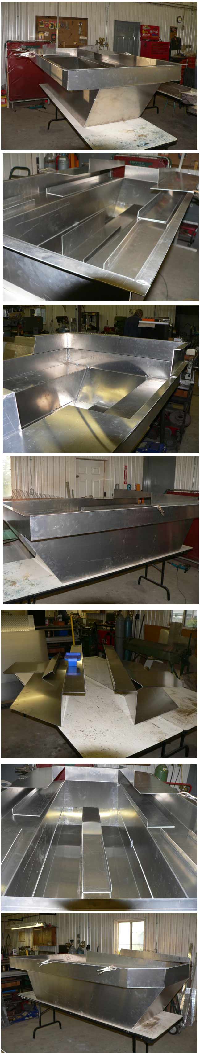
Ok, lets move on. Aluminum is an excellent metal, it’s
light, strong, and doesn’t rust, but it can corrode.
So it needs to be protected from oxidizing. This can be
done via painting, or anodizing. The different alloys
provide excellent strength, weld ability and formability.
I used 5052, this is the same alloy used in dump truck bodies.
Sheet thickness ranged from .063”, .100” and .125”.
I only used 4 sheets total cost for the hull, and hood $430.00
cdn.
If you can, your design should use a lot of bends, this adds
strength and little cost. A 10’ brake is needed
to form the hull, as well as a shear, plasma arc for quick accurate
cuts. Welding can be done via TIG or Aluminum wire feed.
Another method that I didn’t use but considered
was aluminum rivets. Blind rivets are available in a several
sizes that combined with a suitable gasket membrane will make
a strong joint. No need for solid rivets and bucking, this type
you only need a low cost pneumatic riveter.
I started with the hull sides one left hand the other right
(.100”). The bottom was one piece (.125”) with an
overlap on the sides in the bearing area. For the front
and back I used (.100”). So when we put all the
pieces together we have a hull. These are 2 sides, a bottom,
a front and a back. I order to provide extra strength
all joints were fitted with a 1x1x 1/8” angle. This
probably wasn’t needed but did help when fitting all the
parts together, you didn’t need to be so precise when
fitting, and it provided for a fillet lap weld instead of a
butt weld.
For structural integrity you need a longitudinal box beam which
is the backbone of your hull, this beam travels on the centerline
of the bottom of the hull from the bow to the stern. This
beam ties everything together and is stitch welded to the bottom
and to the bow and stern. The other purpose is to reinforce
the hull bottom from impact damage, like rocks, logs etc.
Next is the hood. I believe form should follow function,
not only in shape, but also in design load. So I used
only .063” (1/16”) material for the hood.
You may think that this is too thin a material to use, especially
with a front rack that can easily carry 300 lbs.
However if you look closely you will see that the rack transfers
its entire load to longitudinal beams that actually carry the
load. The only function of the hood, is waterproofing and to
house an exhaust fan. By thinking about this principal
one can have a strong yet light machine.
Ok, so where are we. Well we have a completed hull, and
hood. But we have a few other parts to add to this structure.
Lets do that in the next installment.....
|
 Click image

|
| |
|
|
| |
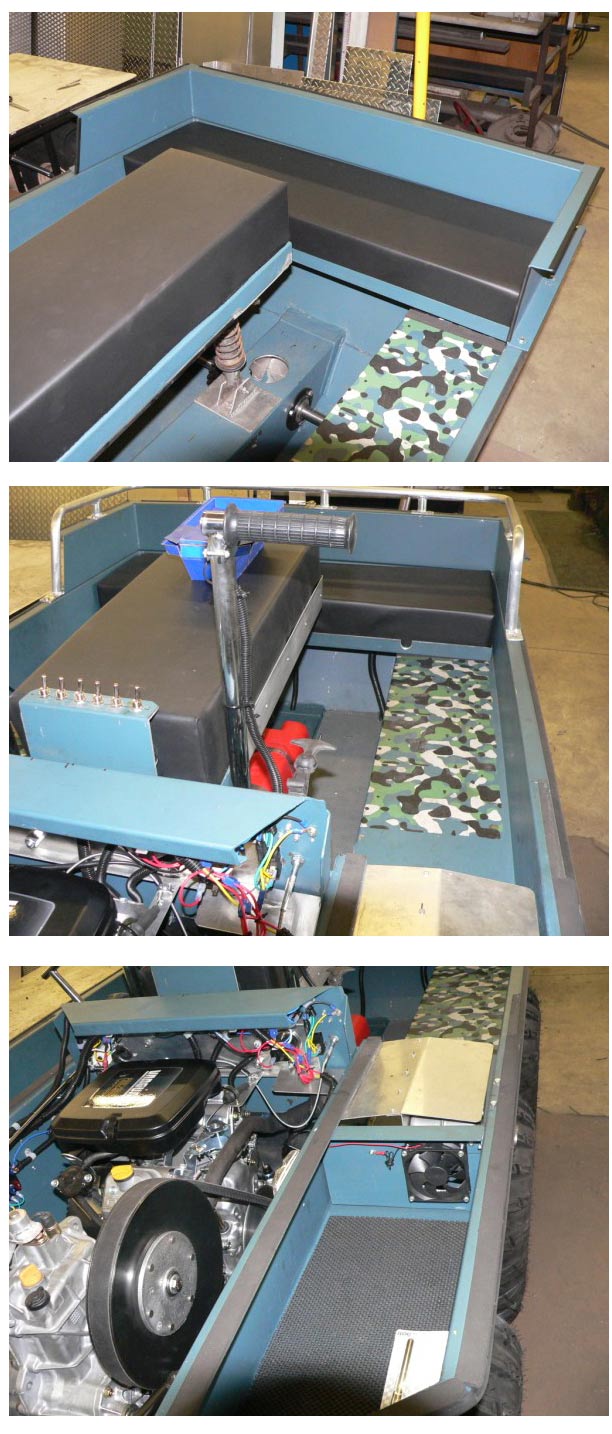
INSTALLMENT #4
Bushwacker ATV
Hull Completion
Now things are starting to take shape, you have a semi-completed
hull that you can admire, no more dreaming you are actually building
your own custom AATV! How will it perform? Will it leak?
How stable will it be in the water and on a side hill? All
these questions and more race through your head, but on with the
task. I found that you need to make some progress everyday;
you need to drive yourself to complete it because you can second
guess yourself, brood over mistakes, and lose interest.
Other thoughts about the costs, your own skills, peoples comments
etc will roll around in your head, you need to focus or you will
never complete it. How many partial completed or abandoned
projects do you know about?
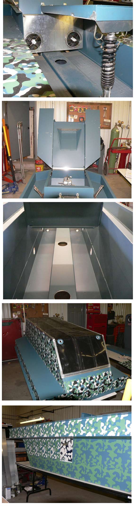
Ok, back to the task on hand. At this point we need to add
some critical parts to the hull. First the main cross beam
that will tie all sides together and also serve as your dash and
seat mount. We need to add a reverse scoop for engine/tranny ventilation.
Also that same crossbeam will serve as a mounting area for the
two-bottom intake cooling fans. This fan housing acts as a firewall
providing separation between the engine area and the rest of the
machine. I made it removable, so if I need more access around
the engine (changing oil filters, spark plug removal etc) I could
get at it. Now lets add the two hood support beams, these
are fabricated from .063” (1/16”) yet once you put
a 90 deg. Bend and weld them in place tying them to the hull and
the firewall they are very strong, yet light. I tried to
make all my parts multi-functional, to reduce the part count,
cost and weight.
For an example lets look at those hood support beams and see what
they are doing. Well their primary function is to support
the hood obviously, but they also provide separation from the
engine compartment, the bend flange on top will have a gasket
to stop any water from entering the engine area, frames in a dry
storage areas on both sides of the machine (gun holder on right
side), and houses the muffler keeping the heat out of the engine
area.
If you look at the stern you will notice an additional piece that
wraps around the rear of the hull and maybe wondering what is
its function. It too is multi-functional. Its main
purpose is to keep water out when exiting a steep bank.
By adding this piece you can safely exist water at a 45 deg. Angle
without taking on any water. It also forms a backrest for
passengers, and a mount for the rear grab rail.
Throughout the whole design/build process I tried to eliminate
any holes in the hull, making all fastener holes above the water
line, thereby eliminating problems. By doing this I can
honestly say that not one drop of water has entered the hull,
the bilge pump job was only removing rain water.
The hull is now basically complete. In the next installment we
will be painting, and bolting parts onto the hull. |
 |
| |
|
|
| |
|
|
| |
|
|
| |
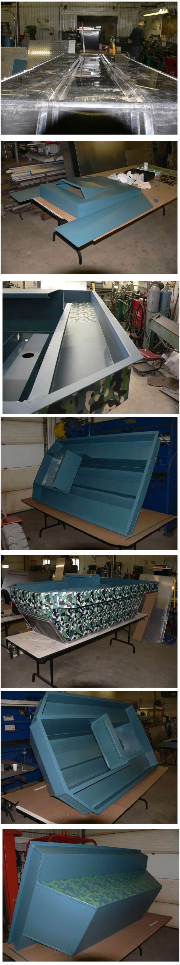
INSTALLMENT #5
Painting, who really enjoys this part, not me but it needs to
be done. I like authentic camo colors, so how do I get what
I want into a paint scheme. Well I did some research and
found a website that allows you to load a “plug-in”
for camo.HERE
You need to run it in a graphics program like photo shop or photo
paint, but it is real cool.
I selected US Army WWII Summer Verdant. Now how do I get
it off the computer screen on to my Bushwacker? Well I figured
out a neat of doing it. First you scale up the pattern to
the size you want using the plugin, then you print it using the
best settings on your color printer. Take this print to
your local paint shop and get them to computer color match it.
Now you have your 4-color camo paint. So now what do I do,
paint all those patterns by hand! No I come up with a relatively
easy way to make stencils using overhead projector slides (transparency
film). This product is available at office depot, staples
and such. Just print out the camo pattern on these transparencies
and cut out the areas for each layer (color). Once you do this
you simply start with the first color, paint the cutout areas
for the first (bottom color) and then repeat for second, third
and forth. It is a long drawn out process, and I don’t
think I would do it again.
Here is what I applied to the bare aluminum: 2 coats etching primer,
2 camo base coats, and 3 other camo colors, and I wonder why I
hate painting!
Ok the painting done, hallelujah. Lets add some parts.
The hood simply gets riveted on using a stainless piano hinge,
it is front opening to allow access for maintenance or inspection.
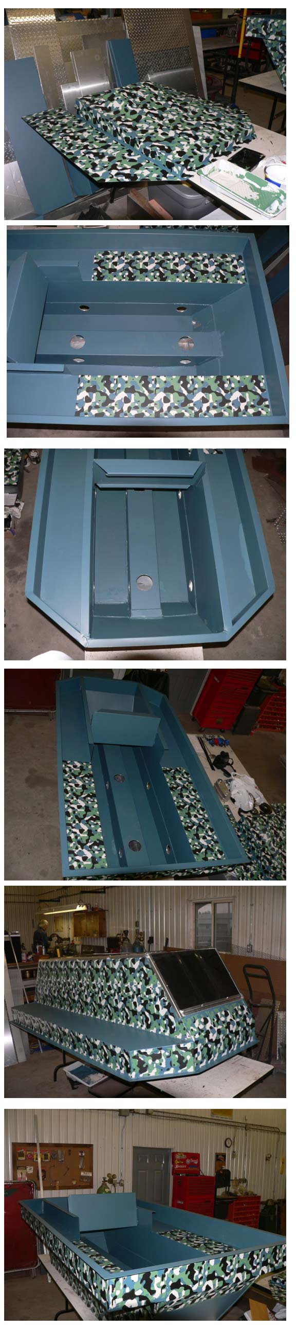
That was easy. What about the bottom or underside of the
Bushwacker how are we going to protect that and not drill any
holes into the hull? Well first we take a sheet of “puckboard”
watch how you spell that one. Puckboard is an inexpensive
HDPE, which comes in a 4x8 sheet for about $35. To add strength
and prevent sagging we will simply put into the brake a few times
to achieve longitudinal creases, which add stiffness. Then
we brake it the other way at both ends so that is hugs the bottom
and goes up the front and back of the hull. Then we bend
up an aluminum angle frame to follow the profile of the bent puckboard
and rivet it to the frame. Then the frame is welded to the
hull at a few points to secure it in place. Now we have
a full “skid plate” to protect the bottom from damage.
The added advantage of the longitudinal creases is that when you
get in muck it breaks the suction, allowing you to stay unstuck.
Remember losing the rubber boots in the mud.
Next we add some drain fittings, I used a pair of brass pipe plugs,
never have to worry about losing a plug.
Now come the dual inlet fans. I located these on the removable
firewall close to the bottom. Cool air is denser/heavier.
These fans and the other 3 run with the key. Screen was
installed to prevent debris from jamming them.
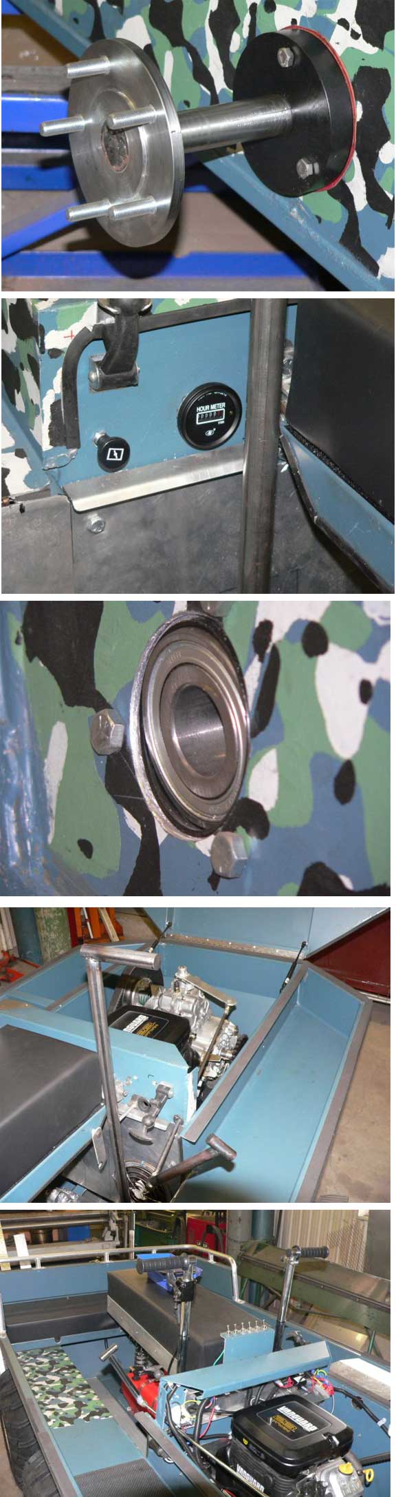
One of the best features that I designed I think was the seat.
It has 5” of the dense foam, and a 5 way adjustable shock.
It also has a 4-position rebound dampener so you can tune it to
your weight. The seat is hinged using 2 pillow block bearings
at one end and a removable pin at the shock shackle to allow the
seat to pivot out of the way for maintenance or access.
It worked beautifully! Once you try a suspension seat you
won’t want anything else. It really gives a softer
ride than a quad. With 3 psi in the tires you swear your
riding on air.
Next installment lets install the drive components… |


|
| |
|
|
| |
|
|
| |
|
|
| |
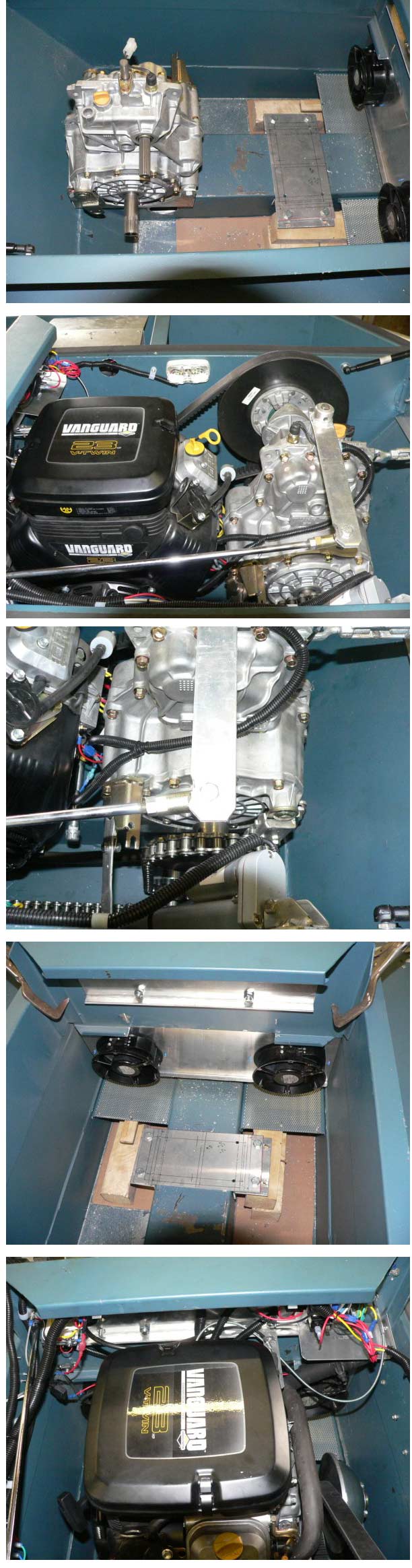
INSTALLMENT #6
Now we come to the drive. We are kind of limited in our
skid steer transmission selection. The choices were T-20,
Argo, Various transaxles, Hydraulic, and the Tuff Torq KT-35.
I will briefly talk about 3 wheel vs. 6 wheel drive. Very
few skid steer transmissions offer 6 wheel drive, the question
to ask is does it have planetary gearing, if the answer is yes
then it will probably be capable of 6 wheel drive. If not
then it probably has bevel gearing in an open differential style
design. This generally means 3 wheel drive. These
two types are represented in the Argo vs. Max scenario in which
arguments have continued for decades! The bottom line is
each one can go where the other goes.
I chose the Tuff Torq KT-35, for the following reasons.
Very high torque ratings, lightweight, proven, splined input/output
shafts, internal wet brakes, levers, neutral switch, no internal
adjustments, simple f-n-r mechanism, and diff. Lock. Yes
it is only 3 wheel drive, however by activating the diff. Lock
it will pretty well go anywhere. I looked at the AV-4 that
uses this transmission but did not install it in the same manner.
My main reasons is the AV-4 uses a direct splined connection to
the rear axle (motor/tranny in rear) which means that the KT-35
would have to sit lower in the hull, which means designing a well
for the bottom to sit in, which reduces ground clearance in that
area. To be fair I should mention that because you are directly
connected to an axle you eliminate a jack shaft, chain, sprockets
etc. This gives you a backup if you ever break a chain,
it will always get you back home! The other reason I didn’t
direct connect was if I wanted to change the final sprocket ratio
I couldn’t. I mounted the KT-35 in a way so I could
adjust the drive belt and the chain attached to it together, in
retro-spect I don’t think this is such a good idea, if I
did it again I would separate them. Meaning I would move
the engine to tighten the belt, and move the KT-35 to tension
the chain.
Ok enough about the tranny, now comes the engine. Well here
we have a lot of selection and a lot of options. I chose
the Vanguard 23 hp, with recoil backup and 50 amp. Stator.
This engine develops very good torque at low rpm and is built
in Japan. Just a footnote, this engine likes to run cool,
if it gets too warm it will run rich, surge and it will lose power,
also it takes a bit of work to bring the idle down.
The engine dimensions are very compact; it’s also less than
90 lbs. I think it is an excellent engine. I rubber mounted
it, for vibrations, however this twin is very smooth running.
I also designed the mounts for side adjustment so I could accurately
allow of the driver/driven offset. Make sure to check with
your supplier i.e.: Comet etc. as to what this dimension is, because
it is critical. If you are out of alignment you will loose
speed, generate heat and wear out your drive belt prematurely.
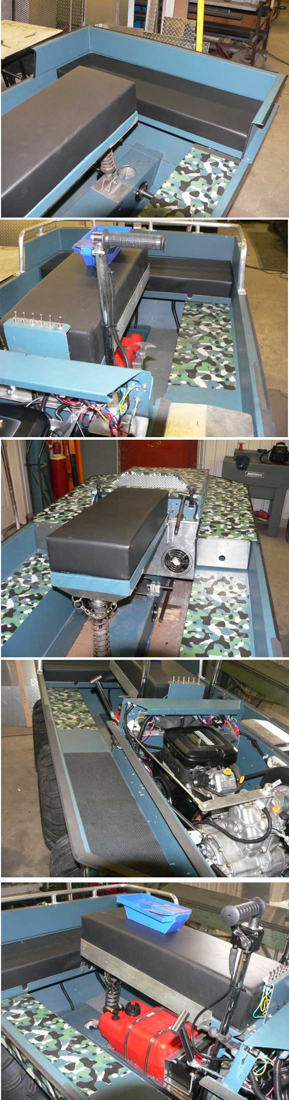
So the engine is mounted, gas line run to it with primer ball,
wiring is all done, what’s next?
It’s time to design and install the exhaust. I didn’t
use the big canister muffler that came with the engine because
it would mean mounting it inside the engine compartment.
Too much heat. So I decided to mount it in part of the left
storage area. I installed the necessary heat shields, but the
hood area above was still getting too hot so I added a small exhaust
fan that blows across the muffler and out side. This pretty
much solved the problem, a $5.00 fix.
So now we have an engine, skid steer transmission ready to go,
the excitement is building, it’s starting to look like a
“real machine”!
In the next installment we will do the shifter, steering levers,
diff. Lock, gas tank, battery, and running boards…..
|


|
| |
|
|
| |
|
|
| |
|
|
| |
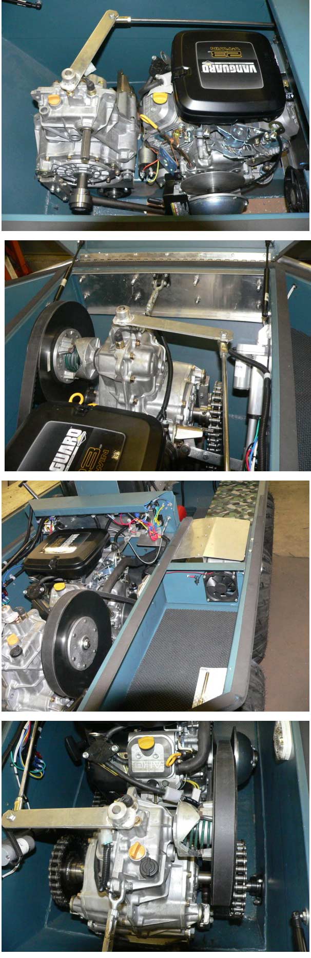
INSTALLMENT #7
The shifter mechanism is very simple, just a level, that attaches
to the top of the KT-35, it has a flat spot on the shaft for a
setscrew. The other end is a “T-handle”, to
grab on to shift. Where is goes through the firewall I installed
a rubber grommet, and a little white lube to reduce friction.
So pull all the way back is forward, move to the next position
pushing in is neutral, push it to the next position is reverse.
That’s it.
The steering levers required a little engineering. I wanted
to reduce the effort required to establish maximum brake force
so rather than using some assist mechanism (booster) I just lengthened
both levers. The existing levers on the KT-35 and the steering
levers themselves. So I can achieve maximum braking force
exerting only 28 lbs pull. I used chrome moly tubing and
heim joints at each end for adjustment. It is a simple trouble
free method for steering control. I like my hands horizontal
on the levers so I designed them that way. Also installed
on the levers are the kill switch, and the thumb throttle.
The KT-35 offers a diff lock. On the JD Gators they use
a lever cable control, similar to a car emergency type handle.
I could have done this but I wanted to try an electric actuator.
I experimented with a “fish scale” to determine the
pull required to engage the diff. Lock and ordered it online.
I then needed a DPDT rocker switch with middle off position to
wire it for reversing. These units are very well engineering,
can be stopped mid stroke and automatically shut off at the end
of travel, very nice! It was nice to have this feature to
lock the diff. And achieve 6-wheel drive, but to tell you the
truth, I rarely used it. With 6 wheels available for traction,
if one side is spinning you simply brake that side and away you
go. I found if you can not move forward of reverse you are
hung up or in loon crap and you’re not going anywhere, so
get out the winch. The only real time you need it is if
you’re coming out of water at an angle to the bank, then
the diff lock will help to drive all the wheels, just keep in
mind that when you engage it you cannot steer.
For the gas tank I used a plastic marine tank, with a quick connect
and primer ball. I also used quick release clamps so one
can quickly remove the tank for filling, or take it to the gas
station. Position is important, think about your weight
and balance. I routed the hose via the hollow tunnel that
runs the entire length of the Bushwacker, that way it is protected
and out of the way. I also ran all the wiring harnesses
in this area.
Running boards are important they should be easy to remove and
have a high friction area to provide good support when you’re
bouncing around. I have one running board on each side running
from just ahead of the firewall all the way to the stern.
I covered them with aluminum expanded metal, which is riveted
on.
If you look at the rear of the Bushwacker you will see a full
width hinged seat, again using 5” dense foam. Its
not a suspension seat, but does the job. I hinged the seat
so that if you’re by yourself and you want to put cargo
in that area the seat can be stowed in the up position.
Another important part of any machine is a “bilge pump”;
I installed it in the stern under the left running board, and
used a bulkhead fitting on the left rear. I can honestly
say that I have never seen a drop of water enter that area, but
you never know so make sure you install one in your machine.
I don’t know why every manufacturer doesn’t install
proper axle seals. I used 2 garter spring rubber coated
axle seals for each half axle. They are housed in a delrin-machined
disk with grease added between the seals. These disks are
then fastened to the hull using 3 bearing bolts and a garlok gasket.
So for water to enter it must travel through 2 seals, grease and
sealed bearings. Now of course over time the seals will wear a
groove in the axle, but 4140 alloy is very tough and hard so that
shouldn’t happen for a long time. However when that
time comes you only need to extend or shorten your axle length
a little bit and you have a brand new surface to work with!
On the final installment we will add a few cosmetic things, like
lights, racks, winch, and take it for a ride…………
|


|
| |
|
|
| |
|
|
 |
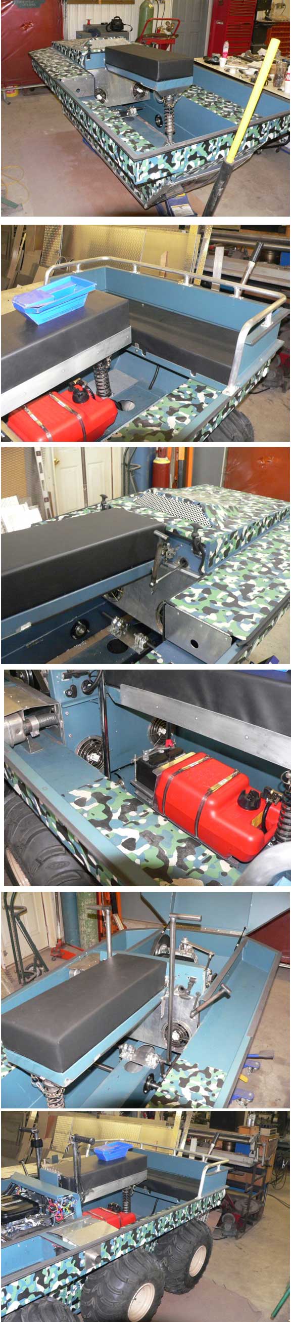
INSTALLMENT #8 Final
section for the Bushwacker
Well we have come a long way from a model Atv to the real thing.
We will be going for a ride shortly, but we need to add a few
things to complete it.
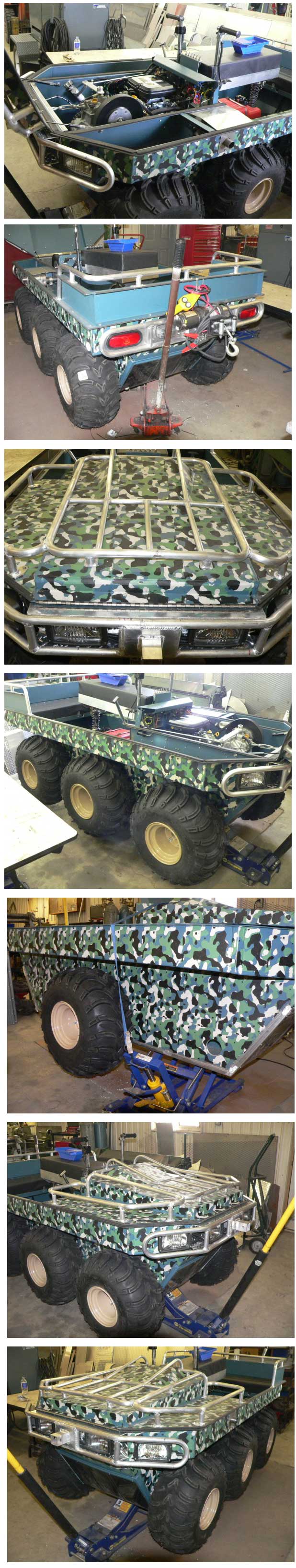
Lights, I took a little different approach I installed 4 headlights.
My idea with the additional two was to mount them at the angle,
which follows the hull shape. My reasoning was because this
is a skid steer vehicle it would be nice to illuminate the trail
off to the sides so I could see what I was turning into.
They worked great!
I also installed taillights, backup lights and an engine compartment
light. For safety and convenience a light is a low cost item but
can be so useful.
Next is the rack, I always appreciated a decent rake, one which
could actually carry a load, and where you have decent tie downs
to fasten things. As you can see by the pics it is functional
and doesn’t look too bad either.
Bumpers not only protect the front and rear lights, but house
the winch receivers, make sure the fasteners are substantial,
with backing plates, you never know how they will be used.
Mine have pushed fair sized trees down and proved out to be pretty
rugged.
Opps, almost forgot the drive chains, nothing different here just
#60 HD chain, with traditional tensioners. The only thing
here that I would change is the tensioners, I probably would try
a neat non-traditional tensioner called a “Reynolds roll
ring” just Google it and you will see one of the best ideas
since sliced bread.
Ok let’s go for a ride. All gassed, oiled, adjusted,
tensioned, primed, ready to turn the key. We use a little
choke and Vroom it has a nice deep throaty sound, I blimp the
throttle a few times, wait for the rpm to drop, put it in forward
and were off! I am going slowly, staying close to civilization,
but ever so slowly getting a little more aggressive. Turn
to the left, right, try the brakes, try reverse all seems normal.
My heart is beating faster as I accelerate, it jumps! The
nose comes up and she takes off, like a bat out of hell, what
acceleration! I am getting a little braver, I take it off
road into some thick stuff I can’t believe I’m still
moving through this stuff, my smile is getting wider. I
shake my head saying to myself well done Bushwacker. Those
25” x 12” x 9” mudlites are very aggressive
tires. I go back to the road, stop and check the chain tension,
and inspect the drive train, everything seems ok. Over the
following months I get even more aggressive, just crashing through
stuff, and it still amazes me where this thing will go.
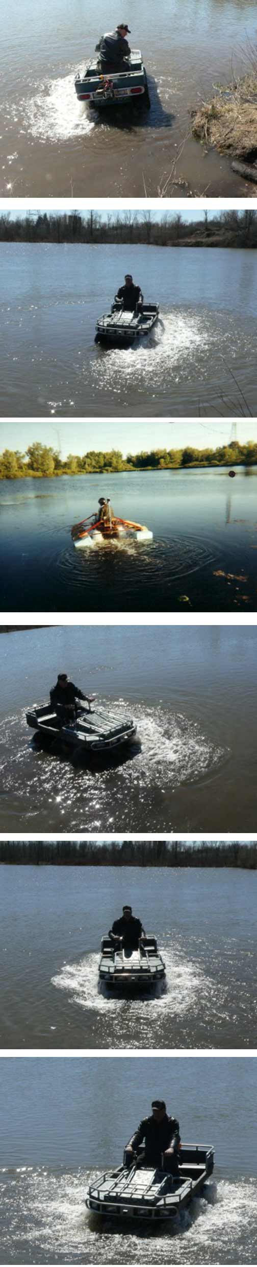
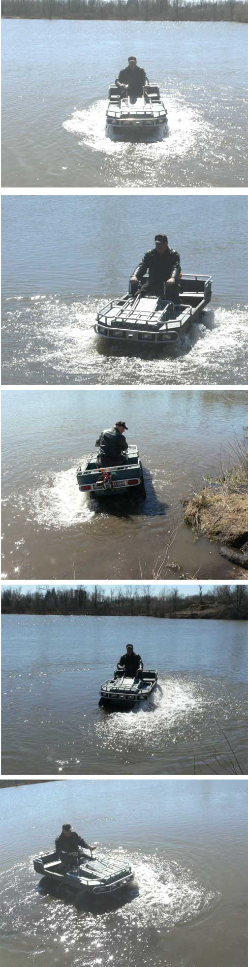
Ok, time for the water test, drain plugs ok, bilge pump works,
throw line ready. I have an assistant ready to pull me in
if it starts to take on water, I’m nervous. I try
to find a shallow grade where I can just ease in the 7-acre pond,
but can’t find one. I edge it forward, the bow starts
to drop down into the water at a relatively steep angle (not really)
my hands are shaking a little, I only have two wheels to go, then
I realize I’m floating! I think I can hear water coming
in, but it’s only my imagination. I’m tense,
I try to relax, but can’t, all my movements are very slow.
It feels tipsy to me, I try to shift my weight but think it’s
going to tip (not really). I do a very large circle, it
takes forever these tires are useless in the water, but over time
and leaning you can make decent tight turns. I have the bilge
pump on but nothing is coming out, my front tires are pawing for
the bank, they grab, I have too much throttle and they pull me
out like a rocket. I find a level spot shut her down and
check for water, not a drop, what a machine!
Over the months I put it through its paces, steep grades, through
swamps, down steep hills, carrying passengers it is a great machine.
Now you may ask if it was such a great machine why did I sell
it. Good question, I ask myself from time to time the same
thing. But in my heart lies the next adventure, driven by
the need to invent and try different things, I’m not so
well off that I could keep it in the stable and move on to my
next project. So I made sure it went to a good home.
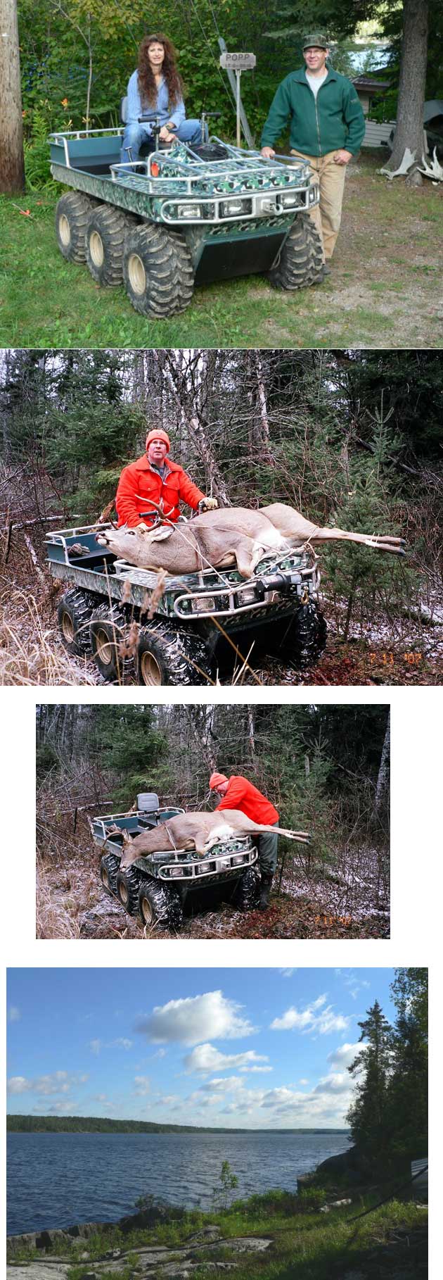
Russ and Pat Popp are the new owners they live in Winnipeg Manitoba
and run a tourist lodge www.bigwoodshunting.com/ located
in a provincial park. They love the Bushwacker and will
make good use of it in their business. They will no doubt
modify it to suit their purpose, and make improvements over time.
I hope you enjoyed the story of the Bushwacker ATV. If you
would like to build one or talk about this fine ATV in more detail
please email me at bisco@rogers.com
Stay tuned for my next project involving a Max II, I’m sure
you will find it interesting! Richard was kind enough to
offer space for its story.
Thank You,
Ray Kohls
London, Ontario |


|
| |
|
|
| |
|
|
| |
|
|
|