 |
|
|
Step - by - Step How to MAX IV Axle Snapring style
This guide is for MAX IV machines with splined snapring
style axles.
Other machines such as MAX II, ARGO, HUSTLER use a similar sytem |
|
This
is another addition to our new how to series, we will ba adding more
every week, so check back often. You may also e-mail suggestions for
future how - to's to. richard@route6x6.com
|
|
 |
Always disconnect battery before servicing machine.
|
 |
Remove disc brake cable cotter pin and swing cable out
of the way
|
 |
Click on PHOTOS to see larger view
|
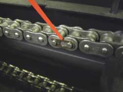 |
Remove the chains master link, unroll chain from sprocket
and set chain aside too.
|
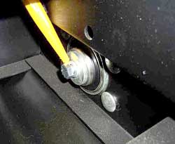 |
Working on the inside, center of frame area, remove the bolt, washers from end of axle.
Note: These bolts keeps axle from pulling out of the bearings as you drive.
Click on PHOTOS to see larger view
|
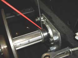 |
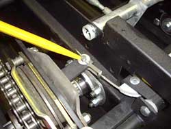
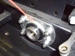
Locate and remove set screw in colar of inner bearing Note:
red pointer
Click on PHOTOS to see larger view
|
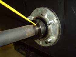 |
Remove
outer locking collar and tap axle out See Removing locking collar bearings
|
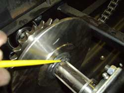 |
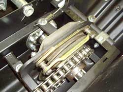
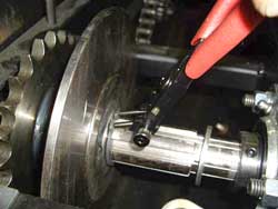
Locate snap ring on inside brake rotor, see yellow pointer.
Click on PHOTOS to see larger view
|
 |
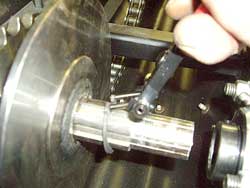
Spread
snap ring with snap ring tool and slide it down the axle. Click on PHOTOS to see larger view
|
 |
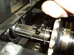
Begin
to slide axle out while removing snap ring and shims from inside end
of axle. Click on PHOTOS to see larger view
|
 |
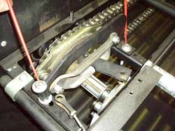
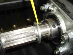
Slide sprocket and brake rotor assembly out of the way and remove outer snap ring and shims
Note:
Shims go against outer snap ring, with sprocket assembly installed clearance
between brake rotor hub and inner snap ring should be .010" gain
correct clearance by adding or removing shims as necessary. All snap
ring axles are set up the same. Click on PHOTOS to see larger view
|
 |
Note: Location and number of shims, this machine has one, some axles will have between 1 and 3 shims
|
 |
Now is a good time to check the inner bearing condition, procedure is same and the outer bearings.
|
We offer all parts shown here at RICHARD'S RELICS
If you have any
questions, you welcome to contact us at richard@route6x6.com Replacement parts
available at RICHARD'S RELICS
ATV Chassis parts page |
|
| Home | About This Site | New Toys | Information Bank | What's New | Blast From The Past | Museum | Tips | Photo Gallery | How To | FAQ'S | Memory Lane | Classifieds | Discussion Boards | Cartoon | Events | Shoppe | Parts for ATV's | Owner Registry | Links Webmaster: For questions or comments
|
|